Boost a Pump Installation Procedures for a GT?


Waldo

GT Owner
Mark IV Lifetime
Sep 7, 2005
770
Fort Worth, TX
I finally got around to ordering a Kenne Bell Boost a Pump to compliment the 4.0 liter Whipple on my GT. The closest instructions Kenne Bell has for a Ford GT are for a GT-500. In other words, the instructions are helpful for explaining the theory of the installation on a GT but not the actual installation.

Can anybody offer up a few pictures or bits of advice as to where to mount the unit, splice into the fuel pump wires, and the best way to route the pressure switch wires? Any assistance would be appreciated.

Best Regards,
Waldo
 

roketman

GT Owner
Mark IV Lifetime
Oct 24, 2005
8,095
ma.
Waldo,
I would email or call the Gt guys or Shelby.
 

BlackICE

GT Owner
Nov 2, 2005
1,416
SF Bay Area in California
I would contact Torrie as he has the most real life experience installing, tuning and using the BAP on his own car. The installation is pretty strait forward with the mounting of the device the hardest in my case, a custom bracket. After it is installed to get the most out of it you will need a modified tune from Torrie or another tuner that is familiar with the product. I am still tuning mine and have some fine adjustments to make before I will be happy.

IMO it is best to install the BAP in between the power feed from the fuel pump relays to the fuel pump driver module and to have it always on (do not use the pressure switch). Also since I know of at lease two failure of the stock fuel pump relays (rated at 15 amps) I choose to have the OEM circuit flip on two additional 40 amp relays using 12g wire instead of the 14g used in the OEM wiring harness. The new relays are fed from a 60amp fuse 8g wire from the battery. The dual BAP is fuse at 30 amps and draws in excess of 20 amps per channel!
 
Last edited:

BlackICE

GT Owner
Nov 2, 2005
1,416
SF Bay Area in California
Photos of BAP installation

The pink/blk and brown/pink 14g wires need to be cut and the BAP inserted in between this point. IMO the beauty installing here is the trouble shooting and maintenance is much easier since you just have to remove the trunk liner vs. the typical mounting location under the passenger side fender liner.
 

Attachments

  • P1010343.jpg
    P1010343.jpg
    104.8 KB · Views: 645
  • P1010351.jpg
    P1010351.jpg
    94.9 KB · Views: 726
  • P1010352.jpg
    P1010352.jpg
    156.7 KB · Views: 669
  • P1010355.jpg
    P1010355.jpg
    138 KB · Views: 666
  • P1010357.jpg
    P1010357.jpg
    145.5 KB · Views: 649
Last edited:

Waldo

GT Owner
Mark IV Lifetime
Sep 7, 2005
770
Fort Worth, TX
Black Ice,

Thanks for the tips and the pictures. That's a very cool installation.

I've got a couple of quick questions for you:

To eliminate the pressure switch, do you simply connect the red and the black wires that would normally be connected to the pressure switch?

Is there any downside to continually running the fuel pumps with 17.5 volts?

Best Regards,
Waldo
 

BlackICE

GT Owner
Nov 2, 2005
1,416
SF Bay Area in California
Black Ice,

Thanks for the tips and the pictures. That's a very cool installation.

I've got a couple of quick questions for you:

To eliminate the pressure switch, do you simply connect the red and the black wires that would normally be connected to the pressure switch?

Is there any downside to continually running the fuel pumps with 17.5 volts?

Best Regards,
Waldo

Yes, I just cut and connected the two wires together and stuffed them back into the BAP case. I hope running 100% of the time isn't bad, because I am using the comp 20V system. :lol My main concern was not the pumps, but the FPDM electronics being overdriven to 20v in my case. Many ICs are spec to run at 18v max; however I felt much better after conversing with Torrie since he is also using a 20V BAP wired always on as well and has over 30K on it without issues. YMMV

Using the switch and having the voltage jumping around would only confuse the ECU when it is also trying to control the pump voltage.
 
Last edited:

Ed Sims

GT Owner
Mark IV Lifetime
Apr 7, 2006
7,926
NorCal
Shadowman is installing my BAP as we speak so it'll be ready to try out at the GT Speed Day.

Ed
 

BlackICE

GT Owner
Nov 2, 2005
1,416
SF Bay Area in California
Shadowman is installing my BAP as we speak so it'll be ready to try out at the GT Speed Day.

Ed

Maybe he will post some pictures of the BAP with the hand model. :lol
 

Waldo

GT Owner
Mark IV Lifetime
Sep 7, 2005
770
Fort Worth, TX
Maybe he will post some pictures of the BAP with the hand model. :lol
Oh, good call. I'll check out his website to see if he's posted any pictures there.
 

2112

Blue/white 06'
Mark II Lifetime
Forgive the ignorance here :frown, The BAP is a totally electronic feature or is there a physical pumping mechanism being added as well?
 

BlackICE

GT Owner
Nov 2, 2005
1,416
SF Bay Area in California
Forgive the ignorance here :frown, The BAP is a totally electronic feature or is there a physical pumping mechanism being added as well?

Totally electronic, all it does is take a nominal 8 to 15v input and jacks it up to 17.5 or 20v to over drive the fuel pumps. Just a dc to dc switching power supply.
 

Fubar

Totally ****** Up
Mark II Lifetime
Le Mans 2010 Supporter
Aug 2, 2006
3,979
Dallas, TX
The concern with leaving it on all the time, is heating the BAP up and causing it to shut itself off. I don't know if this is common enought to be a concern but the area right next to the steering column is not necessarily 'cool'.

It's a trade off, 6 one way, half a dozen the other. If Torrie says always on, then I'd believe him.
 

tmcphail

GT Owner/Vendor
Mark IV Lifetime
Apr 24, 2006
4,103
St Augustine, Florida
I have had BAP's perpetually running since 2003. 0 problems. Run it on all of the time unless you enjoy drivability problems from pressure spikes and drops at pressure point of activation.
 

Waldo

GT Owner
Mark IV Lifetime
Sep 7, 2005
770
Fort Worth, TX
I have had BAP's perpetually running since 2003. 0 problems. Run it on all of the time unless you enjoy drivability problems from pressure spikes and drops at pressure point of activation.
Torrie,
Got it. I'll wire it as such.

Kenne Bell suggested and sent me the 17.5 volt BAP. Should I send it back and exchange it for the 20 volt BAP?

Best regards,
Waldo
 

tmcphail

GT Owner/Vendor
Mark IV Lifetime
Apr 24, 2006
4,103
St Augustine, Florida
I would think that should be sufficient but for what you are doing. I generally advocate the use of the 20v.


Torrie,
Got it. I'll wire it as such.

Kenne Bell suggested and sent me the 17.5 volt BAP. Should I send it back and exchange it for the 20 volt BAP?

Best regards,
Waldo
 

2112

Blue/white 06'
Mark II Lifetime
Torrie, Do you sell these?
 

tmcphail

GT Owner/Vendor
Mark IV Lifetime
Apr 24, 2006
4,103
St Augustine, Florida
Torrie, Do you sell these?

Yes I do.
 

Waldo

GT Owner
Mark IV Lifetime
Sep 7, 2005
770
Fort Worth, TX
OK, it's in and the motor didn't blow...

Since Arizona is back into the 90's, spending the afternoon wrenching on the GT seemed like a better idea then unloading another truck-load of rock for the yard. Many thanks to BlackICE and everyone for your tips and inputs with a special thanks to nota4re for answering my questions and helping me throughout the process.

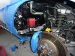
After considering mounting the BAP next to the brake master cylinder, I realized I would rather take a crack at removing the inner fender liner than fabricate a mounting bracket. For those who are contemplating installing one yourself, here's what I did:

1) Lifted the car, removed the front wheel, and applied lots of blue tape to anything that could get scratched.

2) Removed the inner fender liner. Shouting, "Say my name..." and removing all four fasteners at the top of the liner seemed to help. (There are a few threads on the forum that describe the best way to do this.)

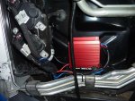
3) Mounted the BAP to the panel below the fuel filler and to the right of the Fuel Pump Driver Modules. I used the machine screws supplied with the kit.

4) Cut the pink/black wire that leads into the connector for the Primary Fuel Pump Driver Module. Connected the red output (non fused) wire from the BAP to the end of the pink/black wire that is leads to the Primary Fuel Pump Driver Module connector. Connected the red input (fused) wire to the end of the pink/black wire that does not lead to the Primary Fuel Pump Driver Module connector.

5) Cut the brown/pink wire that leads into the connector for the Secondary Fuel Pump Driver Module. Connected the blue output (non fused) wire from the BAP to the end of the brown/pink wire that is leads to the Secondary Fuel Pump Driver Module connector. Connected the blue input (fused) wire to the end of the brown/pink wire that does not lead to the Secondary Fuel Pump Driver Module connector.

6) Cut the Boost Switch cable to about 12". Stripped and connected the red and black wires. Wrapped/taped the wires and placed the cable out of the way.

7) Connected the black BAP ground wire to the chassis. I found a dedicated ground below and to the right of the Fuel Pump Driver Modules.

8) Replaced the 15 amp Primary and Secondary Fuel Pump Driver Module fuses in the Auxiliary Relay Box with the 30 amp fuses found in the BAP kit.

9) Turned the ignition key to run. (The BAP made a very slight hum and became slightly warm to the touch.) I hit the start button, and the car started normally.
P1000801b.jpg

P1000799b.jpg

Does anybody know if I can verify the increased fuel pump voltage/output/capacity through the data logging function of a SCT tuner?

Best Regards,
Waldo
 

BlackICE

GT Owner
Nov 2, 2005
1,416
SF Bay Area in California
Does anybody know if I can verify the increased fuel pump voltage/output/capacity through the data logging function of a SCT tuner?

Best Regards,
Waldo

Nice install!


You should log the system after you install you may be surprised. Voltages will be lower than expected, the ECU doesn't really know about the boost in voltage and will tend to have too high of a pressure until the system learns and fills in the fuel pump voltage table. The problem is every time the battery is disconnected or you flash a new tune the learned information is lost.

I will email you some SCT livelink config files to see what is happening.

What I have discovered is that the voltage table should be scaled with the ratio of the 15v divided by new voltage, 15/17.5 or 0.86. Then mulitple each entry by 0.86 as a starting point. Then log the learned values and put back into the tune so that when the battery is disconnector you don't lose that information. Also if you are using a MAfia and have scaled your MAF, engine displacement and injector size, then the fuel pump voltage table's flow on the X axis should be scaled to match. Lastly to squeze more out of your injectors you can increase the fuel pressure under higher engine loads while keeping stock pressures most of the time.

For the more adventuresome you can play with the 3 PID controller values to get a better dynamic pressure response.

For those that don't have tuner software and aren't nerds, call Torrie.
 
Last edited:

Waldo

GT Owner
Mark IV Lifetime
Sep 7, 2005
770
Fort Worth, TX
For those that don't have tuner software and aren't nerds, call Torrie.
Wow... That's great info but having me jump into that and start tweaking things is a disaster waiting to happen. Torrie already tunes my car. I'll just send him another email.

I received your email. I'll hook up my SCT tomorrow and take a look at what my fuel system is doing. Thanks for the files.

Best Regards,
Waldo