Possible gauge protection solution, installation guide
UPDATE 3-30-2015: I now have a schematic at the bottom of this posting. There is an alternative method of configuring the installation. The alternate method involves changing both fuses to the new values shown on the schematic. The idea here is if a voltage overload occurs, the 5 amp fuse will blow completely interrupting the power to the gauges.
If you have not received your order, I am build two more batches and will be shipping them over the next two weeks. Thanks all, Jay
UPDATE 3-24-2015: Due to demand I am going to build another 10 units. If you have not received your order, I will have the remaining units ready to ship by Monday, 3-30-2015. Thanks all, Jay
UPDATE 3-18-2015, 2:50 PM PDT: I am completely sold out of these units! I built and shipped 50 pieces. If there is enough interest I could build another batch someday. Please advise. Thanks, Jay
UPDATE 3-16-2015: Instructions for installing this are outlined at the bottom of this posting.
I am shipping the first batch today. If any of you want to place a last minute order for shipment today please let me know. Also, when dealing with PayPal make sure that your shipping address is included. I will be posting full installation instructions tonight. Also, some of you wanted the polished coil cover fasteners and I will try to include those in the same shipment. Thanks all, Jay
UPDATE 3-13-2015: The units are completed and I am going to test each unit today. Please scroll to the bottom of this posting to view the final product. Jay
3-10-2015: Here is the latest list of potentially interested persons. A couple persons
may want two pieces and those are indicated with that quantity in parenthesis.
The names with question marks after them probably built their own. I am
building a run of 50 units. The cost will be $35.00 plus an $8.00 shipping
and handling fee for domestic shipments totaling $43.00. Overseas shipping
rates will be determined on an individual basis.
Payments may be made via PayPal, please include your shipping address as this does not always show up (gtsaver@cox.net) or by check to:
Jay Philippbar
2006 Via Solona
San Clemente, CA 92673
http://www.analogdesign.com/
Installation Instructions
1. Remove access panel located at foot well on passenger’s side of car. Carefully peel away plastic cover in order to access fuse block.
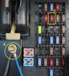
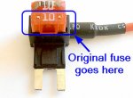
2. Remove 10 amp fuse located at position #28 in fuse block (“B” in Image #1). Install this fuse into the unused location on the fuse adapter as shown in Image #2.
3. Use a 7mm socket to remove the fastener (“A” in Image #1). Reinstall fastener including ring terminal on surge suppressor as shown in Image #3.
4. Install fuse adapter into the location where the fuse was originally located with the red wire coming out of the TOP side (Image #3). Note: The fuse block in this image looks more complicated due to the installation of a wideband A/F ratio gauge.
5. Place plastic cover back in its original position and replace access panel.
6. In the event that the surge suppressor must handle a severe overload, the 10 amp fuse may blow. In this case the upper fuse (Image #2) has a red LED that will glow to indicate a blown fuse (NOTE: the ignition switch must be ON to check this).

Image #1

Image #2

Image #3

Schematics
Last edited:

